D3A Feed Support Design
Introduction
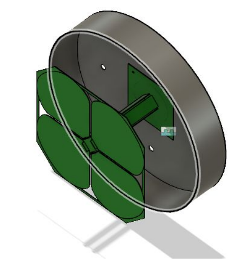
The proposed feed for the D3A dishes is similar to the feed used on the 26-metre telescopes for interferometry with CHIME. This feed has a single CHIME cloverleaf placed in front of a circular ground plane.

Mechanical Requirements
- Translational accuracy and repeatability of 100μm
- Rotational accuracy and repeatability of 1°
- Support the 500g-1000g feed under wind and gravitational load with deflection < 100μm
- Provisions for routing cables in a repeatable position.
- Enclosure for electronics above the feed (about 10,000cm³)
Beam Requirements
In order of importance:
- Induced noise under a couple Kelvin
- Beam repeatability to 1 part in 1000
- Beam difference
Baseline Studies
CST electromagnetic simulations by Ben Saliwanchik considered four cases:
- Feed at focus with no support structure → efficiency = 98.1%
- Feed supported by struts → efficiency = 97.7%
- Feed supported by 5 mm-thick fibreglass tube → efficiency = 95.4%
- Feed supported by 2.5 mm-thick fibreglass tube → efficiency = 98.7%
Case (3) and (4) include a radome. In (4), the tube reduces the beamwidth by ~0.1° and increases the directivity by ~0.3dB.
In these simulations metal was assumed to be lossless (i.e. perfect electrical conductors). The fibreglass was assumed to have these properties:
- ε_r = 6.1 (relative dielectric constant)
- tan δ = 0.0039 (dielectric loss factor)
- μ = 1 (magnetic permeability)
Proposed Solutions
Feed struts
Advantages:
- Possible to avoid using a radome (like on CHIME).
- Struts provide a path for signal and power cable.
- Struts can be attached to the dish on the other side from the support ring, minimizing surface distortions from the load.
Disadvantages:
Central support tube
It is possible support the feed with a post from the centre of the dish (similar to what is done with C-BASS).
Advantages:
- No struts to generate sidelobes
Disadvantages:
- No natural path for cable routing past the feed. There will very likely be scattering off these cables, generating sidelobes on the sky.
- The low angle-of-incidence of rays passing through the tube means that the effective wall thickness is increased, possibly increasing loss and noise.
Here is a cross-section showing this concept. Although the support tube will be made of thin dielectric, the angle of incidence of rays to the feed will be low, enhancing scattering. However, it is worth noting this in this particular scenario that the region of the dish affected is shadowed by the feed.

In this image the diameter of the parabolic reflector is 3 metres and the diameter of the central tube is 15 cm.
-- WinterlandUser - 2019-04-11


