---+ DAN Effect on White Noise
- DAN Effect on White Noise
- Motivation
- Results - 17 Sep 2010
- Perturbing Nuller to Demod synchronization - 23 Sep 2010
- Exploring transfer function at high frequency - 23 Sep 2010
- Transfer function above 1 - Time Delay Hypothesis - 24 Sep 2010
- New Build with Reduced Delay - 26 Sep 2010
- Many DAN Channels - 20 Oct 2010
- DAN Channel - Wide frequency range - 29 Oct 2010
- 8 DAN Channels only - 4 Nov 2010
- 15 DAN Channels - 10 Nov 2010
Motivation
DAN is expected to locally reduce the white noise level by measuring it and canceling it out. This page investigates whether this actually occurs.
Results - 17 Sep 2010
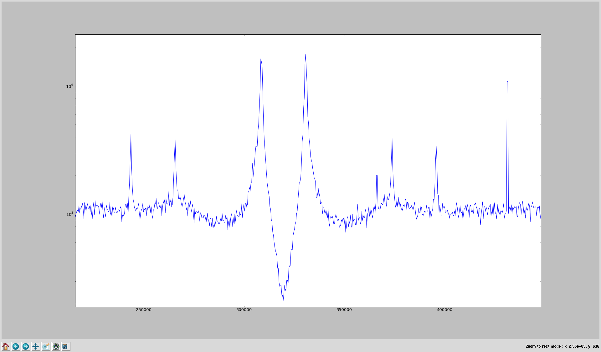
I used a single DAN channel. I then set DMFD rerouting and used another MUX to perform a spectrum analysis for DAN off and DAN on. The resulting plots are shown below.
 |
| Spectrum analysis @ G = 0 |
|---|
 |
| Spectrum analysis @ G = 100 |
|---|
 |
| Spectrum analysis @ G = 100, high resolution |
|---|
As expected, the residual noise level is reduced near the DAN frequency (320 kHz), but it is also increased away from the DAN frequency. Note that the line features away from the "noise reduction region" are actually enhanced when DAN is enabled.
Perturbing Nuller to Demod synchronization - 23 Sep 2010
The nuller I and Q channels must be aligned to the demodulator I and Q channels. My intuition was that the high noise features about 10 kHz away from the nulling frequency might be caused by poor synchronization. This does not appear to be the case.
The effects of perturbing the nuller to demod sync are shown in the plots below.
 |
| Spectrum analysis @ G = 100, default nuller to demod synchronization |
|---|
 |
| Spectrum analysis @ G = 100, nuller leads demod by 10 degrees |
|---|
 |
| Spectrum analysis @ G = 100, nuller lags demod by 10 degrees |
|---|
Exploring transfer function at high frequency - 23 Sep 2010
The plots shown below demonstrate that signals near 10 kHz away from the DAN frequency are amplified, not moved around in frequency space.
 |
| Spectrum analysis @ G = 10, some signals injected |
|---|
 |
| Spectrum analysis @ G = 100, some signals injected |
|---|
Transfer function above 1 - Time Delay Hypothesis - 24 Sep 2010
DAN suppresses at low frequencies but was found to amplify at medium/high frequencies. One model for this is a fixed time delay in the feedback loop. This would cause a phase change with frequency. Together with the falling gain, this could cause a stable region with effective system gain above unity.
The following plots show the results from a Simulink version of DAN in the continuous time approximation. The frequency axis is arbitrary and different between the two plots.
 |
| Simulated spectrum analysis - no delay added to simulation |
|---|
 |
| Simulated spectrum analysis - significant delay added to simulation |
|---|
New Build with Reduced Delay - 26 Sep 2010
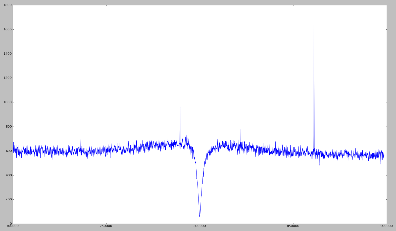
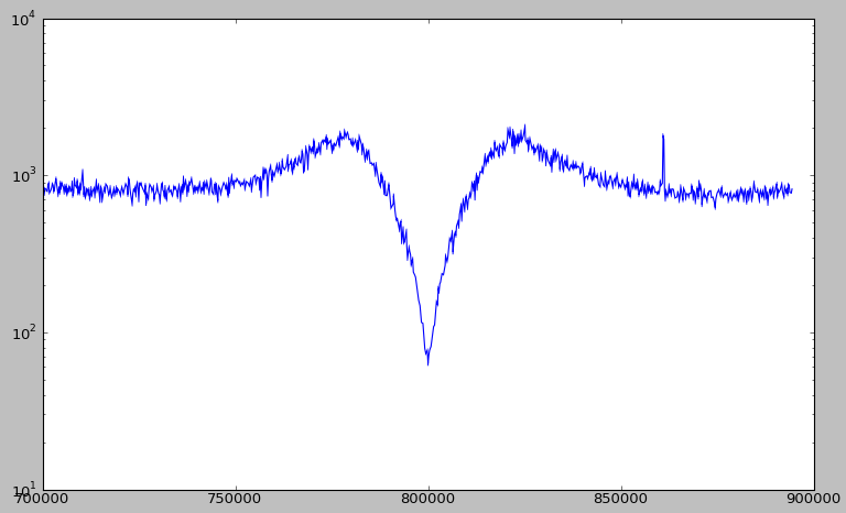
Graeme managed to reduce the delay in the feedback loop by speeding up the clocking of CIC1. In the plot below, all parameters are equal to the "*Spectrum analysis @ G = 100, high resolution*" plot, except for the firmware upgrade.
 |
| Spectrum analysis @ G = 100, New build as of 25 Sep |
|---|
Note the areas of DAN amplification are highly suppressed due to the reduced delay in the feedback loop.
The following plot shows more similar behaviour to that seen before at 6 times higher gain. Somewhat surprisingly the peaks of the amplification region are about a factor 2 further away from the nulling frequency. One hypothesis is that this is due to the breaking down of the continuous-time integrator assumption.
 |
| Spectrum analysis @ G = 600, New build as of 25 Sep |
|---|
Note that the time delay has not been fully eliminated and this is still a source of reduced dynamic range or instability at high gain.
 |
| Spectrum analysis @ G = 1200, New build as of 25 Sep |
|---|
Many DAN Channels - 20 Oct 2010
I set many DAN channels running and took a spectrum analysis. Ideally, this spectrum should show a white noise level with notches at the location of DAN channels. Instead, there seems to be more structure in the spectrum (see figure below).
 |
| Spectrum analysis @ G = 100, 15 DAN channels |
|---|
This structure could be explained by bad synchronization of some channels due to network problems.
Update: Bad synchronization is confirmed by the debugging output. The channels which are confirmed to be poorly synchronized match the peaks in the above spectrum analysis.
DAN Channel - Wide frequency range - 29 Oct 2010
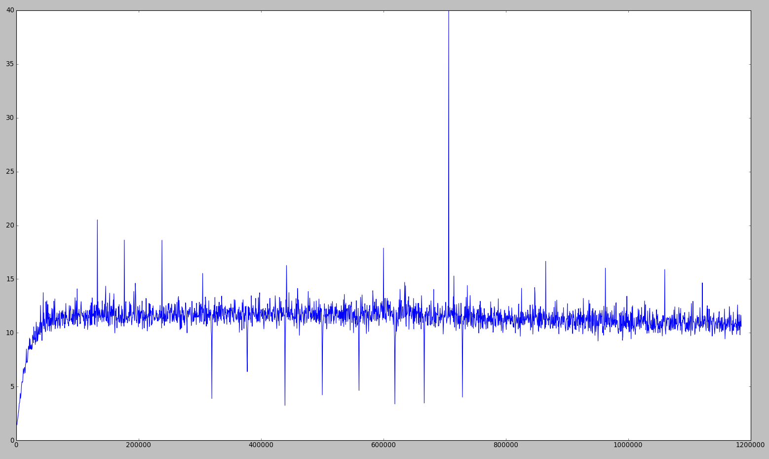
There is some worry that DAN increases noise far outside of the band where it is operating. Plots shown below.
 |
| Wide Spectrum analysis @ G = 0, 1 DAN channel |
|---|
 |
| Wide Spectrum analysis @ G = 100, 1 DAN channel |
|---|
White noise was injected using a function generator. The DAN frequency is 1.8 MHz. I am currently testing the reproducibility of this result.
8 DAN Channels only - 4 Nov 2010
The above problem has been localized to the 17th channel. Using only the first 16 channels, the residual at the ADC is some white noise level, with reduced noise at the location of DAN channels (shown below).
 |
| Wide Spectrum analysis, 8 first DAN channels |
|---|
15 DAN Channels - 10 Nov 2010
Note that the Ch17 problem persists: the channel around 690 kHz does not appear on the plots below.
 |
| Spectrum analysis, 15 first DAN channels G = 100 |
|---|
 |
| Spectrum analysis, 15 first DAN channels G = 1000 |
|---|
 |
| Spectrum analysis, 15 first DAN channels G = 3000 |
|---|
From these plots and the fact that turning the gain up further rails the ADC, it seems we now understand that the instability in the DAN feedback path first occurs when the fixed time delay causes a sufficiently large phase delay at a frequency where the effective gain is still greater than one.
-- TijmenDeHaan - 17 Sep 2010
This topic: ColdFeedback > WebHome > DanWhiteNoise Topic revision: r9 - 2010-11-10 - TijmenDeHaan

